
Techniques > Surveying > Survey Methods > 3D Trilateration
Techniques: 3D Trilateration or the Direct Survey Method (DSM)
Version date: 16 October 2016
Note on Processing with Site Recorder::
3D trilateration measurements need to be processed using Site Recorder software, but this can be done for free as the tools required to do this are available in the Demonstration version.
- Introduction
- Designing Networks
- The 'Everything' Network
Two-dimensional measurement methods like
Offsets and Ties
 Offsets and Ties
Two-dimensional tape survey methods used for assessment surveys and recording detail over a small area
are limited in accuracy, especially over distances of more than 5m, because they are measured from a
tape baseline
Tape Baseline
A tape measure laid between two Control Points
.
For high accuracy survey work or surveys over larger areas three-dimensional trilateration should be used instead. For this method we measure the direct distance between survey points so the accuracy of the survey is is limited by the accuracy of a tape measure. Note that the Direct Survey Method (DSM) is just another name for three-dimensional (3D) trilateration.
In this survey method, a set of distance, depth and position measurements are used to compute the positions of survey points on the site in three dimensions. Direct tape measurements are made between control points and features irrespective of their relative height and a height or depth measurement is also required for every survey point. This method can be used underwater and it works just as well for surveying on land.
Unlike the other techniques this method requires the Site Recorder computer program to process the measurements and calculate the positions of the points. Site Recorder also calculates the accuracy of the position of each point and the errors associated with each measurement allowing you to identify and remove mistakes from the survey. All the capability to process the measurements is available for free using the Demonstration version of Site Recorder.
Once set up this method is very quick and efficient and requires minimal training for the people making the measurements. A very high degree of accuracy can be achieved using this method and this is the most precise and reliable of the techniques which use tape measures. Typical survey accuracy is 20mm for any point on the site but with careful measurements this can be reduced to 10mm.
The drawback to using this method is that it takes time to set up before it can be used and the measurements need processing to get positions for the points.
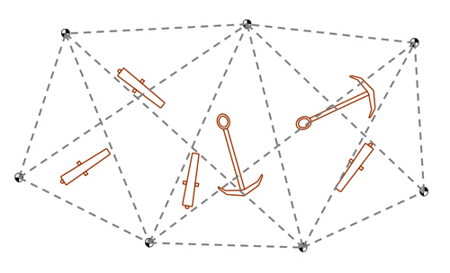
Fig 1: Design the Control point network
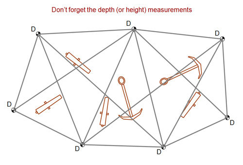
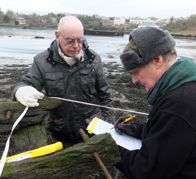
Fig 2: Install the Control Points and make the measurements
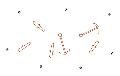
Fig 3: Process the measurements and fix the Control Points in Site Recorder
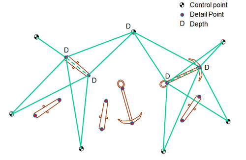
Fig 4: Measure from the Control Points to Detail Points on objects
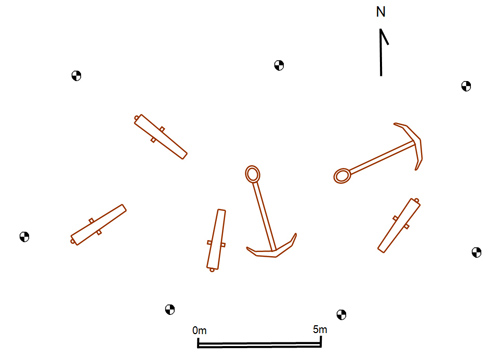 Fig 5: Draw the site plan using the Detail Points as a framework
This method should be used on sites where recording accuracy is important, on older shipwrecks where no plans exist or unique vessels where we can learn about how the ship was constructed.
Getting Started
A trilateration survey is done in two steps; first the Control Point (CP) network is set up then Detail Points on the site are positioned from it, known as the Control/Detail method. Older readers may remember being taught to measure between lots of survey points on the site as one big 'web'. This method should not be used for many reasons, as explained on the page about the Everything Network.
The key to this method is setting up the control points, this first step forms the foundation for the survey and must be correct before moving on. The control points are used as a framework or skeleton for the survey and everything is positioned relative to them. The location of the control points on the site depends on the size and shape of the site itself. The design of control point networks is governed by some simple rules that you can follow, see the page about Designing Networks (Fig. 1).
Making a Sketch
The first exercise is to make a sketch of the site showing its size and shape, the main features on the site and depths or heights across the site. This sketch will be used to plan the position of the control points. Planning can be done in Site Recorder by importing the sketch of the site as a basemap so it can be shown to scale on the chart, survey points can then be added over the sketch and the distances between the points easily checked.
Once designed, the control points need to be installed on the site, with each in the right positron and correctly labelled. The distance measurements between the control points can now be made with a tape measure as defined in the survey plan. Each distance measurement is then added to Site Recorder. The depth or height of each point must be recorded and added as a measurement in Site Recorder (Fig. 2).
With all of the measurements added the positions of the control points can be calculated using the Adjust tool in Site Recorder. The program will calculate the position of the points and will also highlight any measurements that are incorrect; these should be re-measured and the measurement value updated in the program. By repeating this process you will soon end up with a set of measurements that are all correct. With a complete set of good measurements the adjusted positions of the points are now also correct.
Fixing Control Points
It is important to tell Site Recorder that the control point network is good and can be used, this is done by 'fixing' the control points in the program. Fixing a survey point tells the program that it cannot be moved in any subsequent adjustments, particularly in the next step when we use the control points to position many detail points (Fig. 3).
Positioning Detail Points
So the first step in the two step process is now complete. With the control point network installed and positioned we can use it to position detail points on the site. Each detail point can be positioned using distance measurements to four control points plus one depth or height measurement (Fig. 4). Measurements are usually made to the four control points nearest to the detail point, but it is also important to get measurements from all the way around the detail point and not from one side only.
Here the benefit of using the control point network can be seen as it make it much easier to find any bad measurements. Each detail point is positioned separately so a mistake in any one of the measurements is very easily identified and fixed. Measurements are not made between Detail points as this will cause problems in processing if there are mistakes in the measurements, making it much harder to find the bad measurement. Although time is spent setting up the control point network this method is much more efficient than any others as positioning what may be hundreds of detail points becomes very simple.
Method Summary
- Create a sketch of the site
- Plan the control point positions, see Planning Networks
- Install the control points
- Make tape measurements from each point to at least four other points nearby.
- Measure the depth or height of each control point
- Put the measurements into Site Recorder and adjust to compute the positions
- Repeat any measurements as required and re-compute positions
- Fix the position of the control points in Site Recorder
To position each artefact or structure:
- Mark or record the detail points on each feature to be positioned
- Measure from the four nearest control points to each detail point
- Measure the depth or height of each detail point
- Put the measurements into Site Recorder and compute the positions
- Repeat any measurements as required and re-compute
Once all of the detail points have been positioned correctly they can be used to draw up the site plan (Fig. 5). Plan drawings of the main features on the site can be positioned using their detail points. Planning frame drawings can also be positioned using detail points or a baseline between two points.
Equipment List
- Drawing slate - An A4 or A5 size PVC slate, pencil and waterproof paper for making notes
- Pencils - For drawing
- Forms - For recording measurements
- Tape measures - For making measurements
- Compass - A divers hand bearing compass
Related Pages
- Designing 3D Trilateration Networks
- 3D Trilateration - the 'Everything' Network and the Triangle Network
- Positioning using GPS
- Offsets, Ties and Radial Measurements
- Research - How Accurate are Tape Measure Surveys?
- Example - The fireship Firebrand
- Example - The Barrel Wreck
- Example - Re-surveying Coronation (1691)
- Example - Recording the Stella 1 Roman Boat