Techniques > Sites > The A7 Project
Site: Using Site Recorder on the A7 Project
Techniques:Sketching, Photography, Photomosaics, Ultrasonic thickness measurements

|
The A7 Project is an investigation of the early Royal Navy submarine HMS/M A7 lost with all hands during a training exercise in Whitsand Bay, Cornwall, on 16th January 1914.
The project started in October 2013 when the SHIPS Project put a proposal to the UK Ministry of Defence (MoD) to undertake an archaeological investigation of the submarine. The A7 is a Controlled site under the Protection of Military Remains Act 1986 and unauthorised access to the site is prohibited. The project proposal was accepted by the MoD and a license to visit the site was issued to the SHIPS Project for a two month fieldwork season in the summer of 2014.
The aims of the project included undertaking a detailed assessment of the wreck site and a condition assessment of the submarine. Site Recorder was used for all phases of the project: planning, fieldwork, post-ex analysis, reporting and publication.
Planning and Geophysics
At the start of the project very little was known about the A7 submarine site, even its location was not precisely known, so Site Recorder was initially used to collate the information and to plot the published positions on the chart.
The most likely position for the submarine was then used as the centre for a geophysical survey of the site that would result in an accurate position and attitude for the boat. The remains of submarine A7 were mapped using the latest marine geophysical survey techniques, including side scan sonar and multibeam sonar with the assistance of Plymouth University School of Marine Science and Engineering. Images from the surveys were incorporated in Site Recorder and were used as the basis for the site plan (Fig. 1).
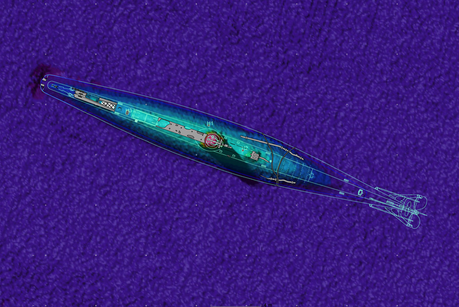
Fig. 1: R2Sonic 700kHz multibeam sonar plan image overlaid with a hull outline in Site Recorder
Fieldwork and Site Plan
The fieldwork to be done on the hull was planned in SR4 so that the tasks could be done efficiently in the short time available to each diver working in 40m depth in poor visibility. The site plan was updated each day so it was always an up to date record of what was known about the hull. Existing plans are often used as a starting point for the site plan when working on a steel ship, but drawings of the outside of this type of submarine do not exist so the features had to be added as they were recorded. When complete the site plan was used to create new engineering drawings for this type of submarine.
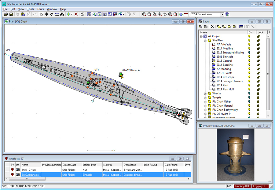
Fig 2: A7 Submarine site plan in Site Recorder
The entire hull was recorded on video using GoPro HERO3+ Black Edition cameras and video lights with detailed areas of the boat recorded as required. Before each dive the divers were briefed and provided with a plan of the hull showing the video images that were needed. Video taken on the site was used on subsequent days to help plan the tasks to be completed and to brief the dive teams.
Still photographs were taken using a Nikon D5200 digital camera fitted with an 11mm rectilinear lens in an Ikelite housing and custom dome port. Natural light was used for wide angle photographs on the rare occasions when visibility was good and two Ikelite DS160 strobe lights were used for detail photographs. An Orcalight Seawolf 2260 canister dive light was loaned to the project for evaluation and this was used to provide wide area floodlighting at a distance from the camera. Trials during work-up dives on other wreck sites showed that the 22000 lumen light could be used to produce better results on deep, dark wrecks than could be achieved using the more usual strobe lights. Unfortunately, the times when the Orcalight was available to be taken onto the A7 site the weather was too poor to allow diving or the visibility on site was too low to be able to use the light effectively.
The short time available on site, poor visibility and potential for narcosis meant that survey work on site had to be as simple as possible. Positioning along the hull was controlled by a simple fibreglass tape baseline fixed between two control points so the tape ran along the top of the hull on the port side. The control points were 10mm stainless steel rods that were pushed into the soft seabed with one on the centreline of the submarine just forward of the bow and one on the centreline aft close to the upper rudder bracket. Errors in the measurements along the tape caused by the change in height of the tape along the curved hull were corrected during post-processing. Detailed measurements and sketches were made of particular features on the hull and conning tower and any areas of damage. Some very limited seabed probing was done at the bow to confirm that both torpedo tube doors were closed and at the stern to check if the rudder and hydroplanes were still in place.
Engineering Drawings
A search for engineering drawings of the first Royal Navy A class submarines located general internal plans for A1, for the second batch A2-A4 and for the unique A13 with its diesel engine in the archives of the National Maritime Museum, Greenwich. No plans showing the external features of this class have been located in any of the archives consulted and no plans at all were found for the third batch (A5-A12) which includes A7.
A set of external general arrangement engineering drawings for the A7 were completed by the A7 Project team using a combination of all of the information available to the project. The plans show the external view of the visible hull only so does not include detail for any part of the hull currently buried in the seabed or any of the internal fittings. One set of plans shows the submarine as it was at the time of loss and a second set show the submarine as it is today.
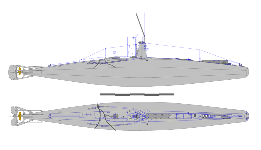
Fig 3: Engineering drawing of A7 drawn using Site Recorder, showing the 2014 condition overlaid with original 1914 features (blue lines)
Reporting
Site Recorder was also used to produce illustrations for the published report and the project web site. The elevation hull drawings were used to create a series of illustrations showing how the submarine sank and how it ended up on the seabed (Fig. 4). The plan chart was also used to create a historical chart showing the events that happened on the day the submarine was lost (Fig. 5). The program was also used to create the project logo shown at the top of this page.
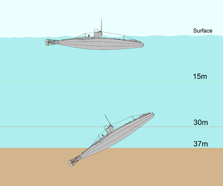
Fig 4: A7 as she was found partly buried in the seabed, also showing working depth (15m) and maximum operating depth (30m)
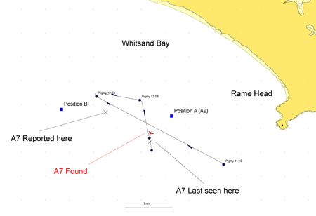
Fig 5: Chart showing the last known location of A7, the reported location of A7 and where she was eventually found
Electronic Publication
The results of the research, geophysics and fieldwork were published in a traditional paper report as part of the BAR British Series. But the digital archive has also been made available as an electronic publication (ePublication), which includes a multi-layer digital site plan, geophysics data, finds records, survey data, records and events. All of these records are accessible in one place using Site Recorder. The archive can be viewed on a PC using the free Site Reader viewer software.
The digital archive is available as a single file to download but it contains all of the files linked to the archive as well as the main archive file itself. Once opened in Site Recorder the file is unpacked, the linked files put in the correct folders and the archive file is displayed. If the archive is opened using the free viewer program called Site Reader then the contents of the archive cannot be altered or added to. If the archive is opened in a licensed copy of Site Recorder then full access to the archive is allowed including editing and exporting in other file formats.
See the A7 Project web site - ePublication

