
Techniques > Sites > Laira Bridge Wreck
Site: Mapping the Laira Bridge Wreck (1940s)
Techniques: Offset, Sketching, Photography, Metal wreck

|
The SHIPS Project have been recording all of the known shipwrecks near Plymouth as part of a wide-ranging study of the maritime heritage in the area. The work includes recording the wrecks on the foreshore as well as underwater.
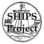
The wreck of a steel barge lying alongside the Laira road bridge over the river Plym uncovers at low water on a spring tide (Fig. 1). The barge is small, does not have an engine and is one of many similar vessels abandoned along the rivers and creeks around Plymouth. But this site is easily accessible and the seabed it lies on is firm sand you can walk on so the wreck is often used for survey training and mapping experiments.
Aims
The aim of this survey was to produce a very basic record of the current state of the wreck. The work should use simple survey and recording methods to produce a plan view of the wreck that records basic dimensions and features. For simplicity the height differences across the site have been ignored.
More complex methods such as using a total station or 3D photogrammetry would produce a better record of this site but for this exercise the most simple methods were used.
Click on any small image below to show a larger version.
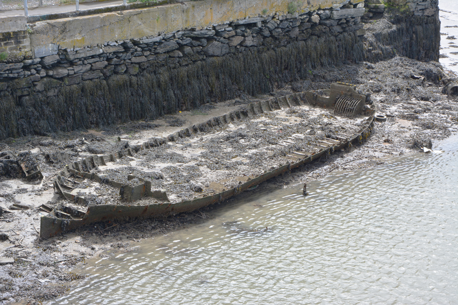
Fig 1: The Laira Bridge Wreck, as seen from the bridge
Fig 2: Measuring offsets from a baseline using a tape measure
Method
Only a very simple plan of the wreck site was required so simple recording and surveying methods were used, these include sketching, offset measurements plus photographs of particular features (Fig. 2)..
A tape measure was laid as a baseline through the middle of the wreck (C1 - C2). The baseline could not be laid in the middle of the ship over the keel as a tall structure at the stern was in the way. So the baseline was laid from the stem post aft so it lay alongside the structure and the stern post was positioned using an offset measurement (Point C16, Fig. 3). The wreck is small and the distances to measure were short so offsets were used instead of tie measurements.
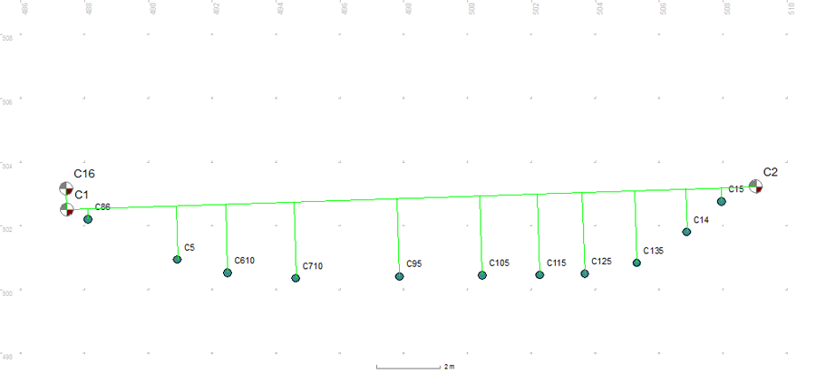
Fig 3: Offset measurements from the baseline used to record the outline of the hull
Offset measurements from the baseline were used to form an outline of the hull. The hull is a very simple shape so only a few measurements were needed to create the outline (Fig. 4). The detail around the bow at control point C2 was added from photographs.
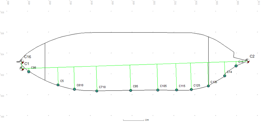
Fig 4: The hull outline drawn using the offset point positions as a guide
Detail survey points were used to position features on the bow and stern of the wreck, again positioned by offset measurements.
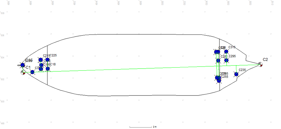
Fig 5: Features on the barge are located using detail points positioned with offset measurements
The spacing between the deck beams running across the ship was measured so they could be added to the plan. Two small areas of steel deck at the bow and stern were also added (Fig. 6).
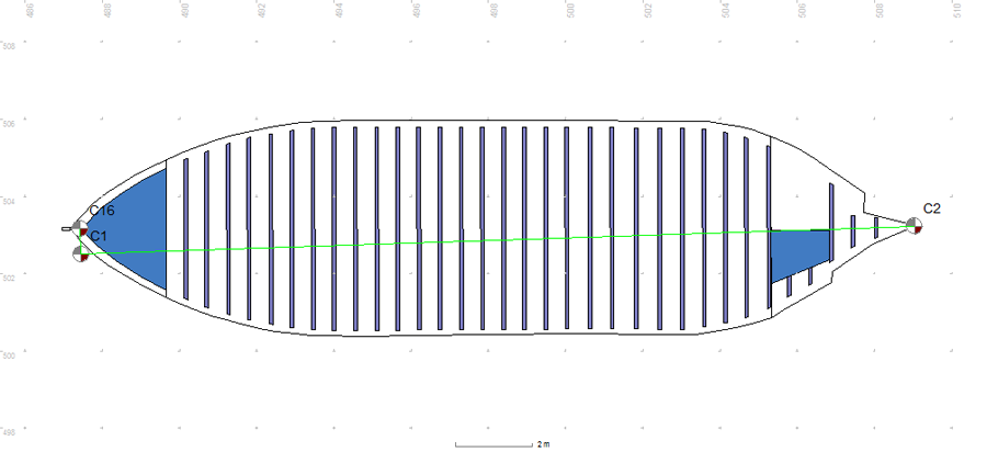
Fig 6: Frames and steel decking drawn on the site plan
The remains of the timber deck in the hold of the ship were drawn. The timber extends under the sand and silt that fill the bow end of the hold but the extents are unknown. The area covered by sediment was drawn in over the deck beams producing the completed site plan.
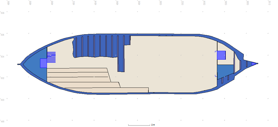
Fig 7: The completed site plan in Site Recorder
Sketches and photographs were taken of features on the hull as they could be used to record particular details not easily captured by basic measurements. A 1m long scale was included in the photographs so dimensions could be taken and to make the photographs more understandable to people who had not seen the site. The scale in Fig. 8 was made from 10mm square aluminium tubing that was covered in alternate 100mm wide bands of yellow and black electrical tape.

Fig 8: Detail plan photograph of the hull and frames

Fig 9: Detail plan photograph of the bow
The plan was drawn in Site Recorder starting with the outline of the hull. Deck and beams were drawn on separate layers to make it easy to change the colour of all of them at the same time when choosing the final colour scheme for the site plan. Next were added the features, again on a separate layer so they could be highlighted in a different colour . The overall hull shape was coloured to be darker to make the frames, details and deck stand out in the final plan (Fig. 10).
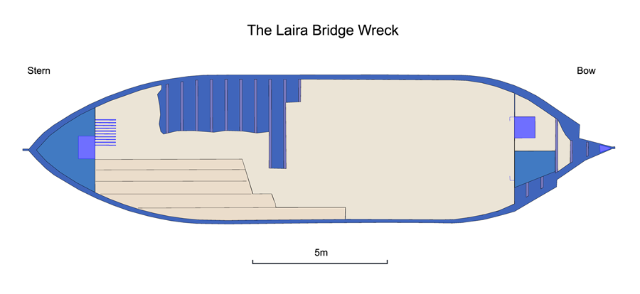
Fig 10: The final site plan exported from Site Recorder as a PDF file
The finished site plan was printed from Site Recorder as a high resolution A2 size PDF document then exported from Adobe Acrobat as a TIFF image. Adobe Photoshop was used to add the scale bar and labels.
This recording exercise used simple methods and produced a simple but useful two-dimensional plan of this site. The wreck has changed each visit with more of the sediment in the hold washed away or some part of the structure collapsed or missing. This plan is a record of the wreck in 2014 that can be adapted as the condition of the site deteriorates.